d3d12龙书阅读----绘制几何体(上) 课后习题
发布: 更新时间:2024-05-19 18:50:08
d3d12龙书阅读----绘制几何体(上) 课后习题
练习1 完成相应的顶点结构体的输入-布局对象
typedef struct D3D12_INPUT_ELEMENT_DESC
    {
    一个特定字符串
    将顶点结构体数组里面的顶点映射到顶点着色器的输入签名
    LPCSTR SemanticName;
    语义索引 如果语义名相同的话 使用索引进行区分
    UINT SemanticIndex;
    顶点元素的格式 与顶点结构体元素的大小相对应
    DXGI_FORMAT Format;
    输入槽索引
    UINT InputSlot;
    代表着顶点结构体各元素的偏移量
    UINT AlignedByteOffset;
    D3D12_INPUT_CLASSIFICATION InputSlotClass;
    UINT InstanceDataStepRate;
    } 	D3D12_INPUT_ELEMENT_DESC;
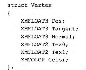
而对于上图中的顶点结构体 顶点输入布局描述如下:
inputLayoutDesc =
{
    { "POSITION", 0, DXGI_FORMAT_R32G32B32_FLOAT,    0, 0,  D3D12_INPUT_CLASSIFICATION_PER_VERTEX_DATA, 0 },
    { "TANGENT",  0, DXGI_FORMAT_R32G32B32_FLOAT,    0, 12, D3D12_INPUT_CLASSIFICATION_PER_VERTEX_DATA, 0 },
    { "NORMAL",   0, DXGI_FORMAT_R32G32B32_FLOAT,    0, 24, D3D12_INPUT_CLASSIFICATION_PER_VERTEX_DATA, 0 },
    { "TEXCOORD", 0, DXGI_FORMAT_R32G32_FLOAT,       0, 36, D3D12_INPUT_CLASSIFICATION_PER_VERTEX_DATA, 0 },
    { "TEXCOORD", 1, DXGI_FORMAT_R32G32_FLOAT,       0, 44, D3D12_INPUT_CLASSIFICATION_PER_VERTEX_DATA, 0 },
    { "COLOR",    0, DXGI_FORMAT_R32G32B32A32_FLOAT, 0, 52, D3D12_INPUT_CLASSIFICATION_PER_VERTEX_DATA, 0 }
};
练习2 使用多个输入槽
主要分为两步 第一步不详细贴代码了 主要是对辅助几何结构体进行更改 将vertex拆分成位置与颜色:
struct MeshGeometry
{
	std::string Name;
	Microsoft::WRL::ComPtr<ID3DBlob> PositionBufferCPU = nullptr;
    Microsoft::WRL::ComPtr<ID3DBlob> ColorBufferCPU = nullptr;
	Microsoft::WRL::ComPtr<ID3DBlob> IndexBufferCPU  = nullptr;

    Microsoft::WRL::ComPtr<ID3D12Resource> PositionBufferGPU = nullptr;
	Microsoft::WRL::ComPtr<ID3D12Resource> ColorBufferGPU = nullptr;
	Microsoft::WRL::ComPtr<ID3D12Resource> IndexBufferGPU = nullptr;

	Microsoft::WRL::ComPtr<ID3D12Resource> PositionBufferUploader = nullptr;
    Microsoft::WRL::ComPtr<ID3D12Resource> ColorBufferUploader = nullptr;
	Microsoft::WRL::ComPtr<ID3D12Resource> IndexBufferUploader = nullptr;

	UINT VertexPosByteStride = 0;
	UINT VertexPosBufferByteSize = 0;
    UINT VertexColorByteStride = 0;
    UINT VertexColorBufferByteSize = 0;
	DXGI_FORMAT IndexFormat = DXGI_FORMAT_R16_UINT;
	UINT IndexBufferByteSize = 0;

	std::unordered_map<std::string, SubmeshGeometry> DrawArgs;

    D3D12_VERTEX_BUFFER_VIEW PositionBufferView()const
    {
        D3D12_VERTEX_BUFFER_VIEW pbv;
        pbv.BufferLocation = PositionBufferGPU->GetGPUVirtualAddress();
        pbv.StrideInBytes = VertexPosByteStride;
        pbv.SizeInBytes = VertexPosBufferByteSize;

        return pbv;
    }

    D3D12_VERTEX_BUFFER_VIEW ColorBufferView()const
    {
        D3D12_VERTEX_BUFFER_VIEW cbv;
        cbv.BufferLocation = ColorBufferGPU->GetGPUVirtualAddress();
        cbv.StrideInBytes = VertexColorByteStride;
        cbv.SizeInBytes = VertexColorBufferByteSize;

        return cbv;
    }

	D3D12_INDEX_BUFFER_VIEW IndexBufferView()const
	{
		D3D12_INDEX_BUFFER_VIEW ibv;
		ibv.BufferLocation = IndexBufferGPU->GetGPUVirtualAddress();
		ibv.Format = IndexFormat;
		ibv.SizeInBytes = IndexBufferByteSize;

		return ibv;
	}

	void DisposeUploaders()
	{
        PositionBufferUploader = nullptr;
        ColorBufferUploader = nullptr;
		IndexBufferUploader = nullptr;
	}
};
第二步在draw函数中使用不同的输入槽进行绘制:
mCommandList->IASetVertexBuffers(0, 1, &mBoxGeo->PositionBufferView());

mCommandList->IASetVertexBuffers(1, 1, &mBoxGeo->ColorBufferView());
练习3 使用不同的图元拓扑 练习8 使用线框模式 练习9 背面与正面剔除
这里启用线框模式可以帮助我们更好的观察
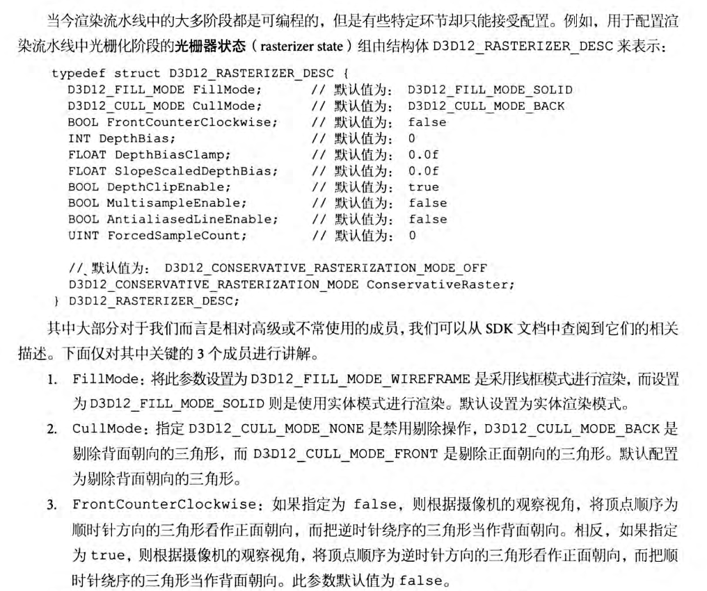
只需要在buildPSo函数中对光栅器状态进行修改即可
背面与正面剔除的设置也在这里修改
使用不同的图元拓扑在:
mCommandList->IASetPrimitiveTopology(D3D11_PRIMITIVE_TOPOLOGY_TRIANGLELIST)
修改即可
练习4 绘制金字塔
定义顶点数组 与 索引数组
这里要特别注意索引顺序 看不见的面使用逆时针
看见的面使用顺时针
std::array<Vertex, 5> pyramid_vertices =
{
    Vertex({ XMFLOAT3(-1.0f, 0.0f, -1.0f), XMFLOAT4(Colors::Green) }),
    Vertex({ XMFLOAT3(-1.0f, 0.0f, 1.0f), XMFLOAT4(Colors::Green) }),
    Vertex({ XMFLOAT3(+1.0f, 0.0f, -1.0f), XMFLOAT4(Colors::Green) }),
    Vertex({ XMFLOAT3(+1.0f, 0.0f, 1.0f), XMFLOAT4(Colors::Green) }),
    Vertex({ XMFLOAT3(0.0f, 2.0f, 0.0f), XMFLOAT4(Colors::Red) })
};

std::array<std::uint16_t, 18> pyramid_indices =
{
    // 底面 逆时针
    0, 2, 1,
    1, 2, 3,

    // 侧面 顺时针
    1, 4, 0,
    0, 4, 2,
    2, 4, 3,
    // 背面 逆时针
    1, 3, 4
};
练习6 设置常量gTime

修改如下:
struct ObjectConstants
{
    XMFLOAT4X4 WorldViewProj = MathHelper::Identity4x4();
    float gTime = 0.0f;
};
然后在update函数进行相应修改:
ObjectConstants objConstants;
XMStoreFloat4x4(&objConstants.WorldViewProj, XMMatrixTranspose(worldViewProj));
objConstants.gTime = gt.TotalTime();
mObjectCB->CopyData(0, objConstants);
练习7 将金字塔与立方体合并到一个大的顶点缓冲区与索引缓冲区 同时使用不同的世界矩阵使得两者互不相交
本题的方法可以在完成第七章的学习之后再来看
我们可以先从初始化开始:
 BuildDescriptorHeaps();
BuildConstantBuffers();
 BuildRootSignature();
 BuildShadersAndInputLayout();
 BuildBoxGeometry();
 BuildPSO();
第一步 构建常量缓冲区描述符堆(因为我们这里根签名还是采用描述符表的形式 所以需要构建描述符堆来存储 cbv描述符)
因为之前只绘制一个物体 而这里要绘制两个物体 每个物体都需要一个常量数据对应的描述子:
 D3D12_DESCRIPTOR_HEAP_DESC cbvHeapDesc;
 cbvHeapDesc.NumDescriptors = 2;//修改为2  这里就不再改为更通用的表示 第七章示例代码已经做出了示范
 cbvHeapDesc.Type = D3D12_DESCRIPTOR_HEAP_TYPE_CBV_SRV_UAV;
 cbvHeapDesc.Flags = D3D12_DESCRIPTOR_HEAP_FLAG_SHADER_VISIBLE;
	cbvHeapDesc.NodeMask = 0;
 ThrowIfFailed(md3dDevice->CreateDescriptorHeap(&cbvHeapDesc,
     IID_PPV_ARGS(&mCbvHeap)));
第二步 构建常量缓冲区视图
void BoxApp::BuildConstantBuffers()
{
	mObjectCB = std::make_unique<UploadBuffer<ObjectConstants>>(md3dDevice.Get(), 2, true);

	UINT objCBByteSize = d3dUtil::CalcConstantBufferByteSize(sizeof(ObjectConstants));
    D3D12_GPU_VIRTUAL_ADDRESS cbAddress = mObjectCB->Resource()->GetGPUVirtualAddress();
    for (UINT i = 0; i < 2; ++i)
    {
        // 偏移到第i个物体常量数据
        cbAddress += i * objCBByteSize;

        // 偏移到对应的描述符堆的第i个cbv
        int heapIndex = i;
        auto handle = CD3DX12_CPU_DESCRIPTOR_HANDLE(mCbvHeap->GetCPUDescriptorHandleForHeapStart());
        handle.Offset(heapIndex, mCbvSrvUavDescriptorSize);

        D3D12_CONSTANT_BUFFER_VIEW_DESC cbvDesc;
        cbvDesc.BufferLocation = cbAddress;
        cbvDesc.SizeInBytes = objCBByteSize;

        md3dDevice->CreateConstantBufferView(&cbvDesc, handle);
    }
}
第三步 构建根签名 不变 要记住我们还是只使用了一个常量缓冲区来存储不同物体的常量数据 对应着色器的b0 而在第七章这里发生变化 因为使用了两个常量缓冲区 一个物体一个过程 对应着色器的b0 b1
第四步 着色器设置 与顶点输入布局描述设置 不变
第五步 构建box几何体 要变 需要设置两个物体的顶点 与 索引缓冲区 并且合并
void BoxApp::BuildBoxGeometry()
{
    std::array<Vertex, 8> box_vertices =
    {
        Vertex({ XMFLOAT3(-1.0f, -1.0f, -1.0f), XMFLOAT4(Colors::White) }),
		Vertex({ XMFLOAT3(-1.0f, +1.0f, -1.0f), XMFLOAT4(Colors::Black) }),
		Vertex({ XMFLOAT3(+1.0f, +1.0f, -1.0f), XMFLOAT4(Colors::Red) }),
		Vertex({ XMFLOAT3(+1.0f, -1.0f, -1.0f), XMFLOAT4(Colors::Green) }),
		Vertex({ XMFLOAT3(-1.0f, -1.0f, +1.0f), XMFLOAT4(Colors::Blue) }),
		Vertex({ XMFLOAT3(-1.0f, +1.0f, +1.0f), XMFLOAT4(Colors::Yellow) }),
		Vertex({ XMFLOAT3(+1.0f, +1.0f, +1.0f), XMFLOAT4(Colors::Cyan) }),
		Vertex({ XMFLOAT3(+1.0f, -1.0f, +1.0f), XMFLOAT4(Colors::Magenta) })
    };

	std::array<std::uint16_t, 36> box_indices =
	{
		// front face
		0, 1, 2,
		0, 2, 3,

		// back face
		4, 6, 5,
		4, 7, 6,

		// left face
		4, 5, 1,
		4, 1, 0,

		// right face
		3, 2, 6,
		3, 6, 7,

		// top face
		1, 5, 6,
		1, 6, 2,

		// bottom face
		4, 0, 3,
		4, 3, 7
	};
    std::array<Vertex, 5> pyramid_vertices =
    {
        Vertex({ XMFLOAT3(-1.0f, 0.0f, -1.0f), XMFLOAT4(Colors::Green) }),
        Vertex({ XMFLOAT3(-1.0f, 0.0f, 1.0f), XMFLOAT4(Colors::Green) }),
        Vertex({ XMFLOAT3(+1.0f, 0.0f, -1.0f), XMFLOAT4(Colors::Green) }),
        Vertex({ XMFLOAT3(+1.0f, 0.0f, 1.0f), XMFLOAT4(Colors::Green) }),
        Vertex({ XMFLOAT3(0.0f, 2.0f, 0.0f), XMFLOAT4(Colors::Red) })
    };

    std::array<std::uint16_t, 18> pyramid_indices =
    {
        // 底面 逆时针
        0, 2, 1,
        1, 2, 3,

        // 侧面 顺时针
        1, 4, 0,
        0, 4, 2,
        2, 4, 3,
        // 背面 逆时针
        1, 3, 4
    };

    UINT boxVertexOffset = 0;
    UINT pyramidVertexOffset = (UINT)box_vertices.size();

    UINT boxIndexOffset = 0;
    UINT pyramidIndexOffset = (UINT)box_indices.size();

    SubmeshGeometry boxSubmesh;
    boxSubmesh.IndexCount = (UINT)box_indices.size();
    boxSubmesh.StartIndexLocation = boxIndexOffset;
    boxSubmesh.BaseVertexLocation = boxVertexOffset;

    SubmeshGeometry pyramidSubmesh;
    pyramidSubmesh.IndexCount = (UINT)pyramid_indices.size();
    pyramidSubmesh.StartIndexLocation = pyramidIndexOffset;
    pyramidSubmesh.BaseVertexLocation = pyramidVertexOffset;

    auto totalVertexCount =
        box_vertices.size() +
        pyramid_indices.size();

    std::vector<Vertex> vertices(totalVertexCount);

    UINT k = 0;
    for (size_t i = 0; i < box_vertices.size(); ++i, ++k)
    {
        vertices[k].Pos = box_vertices[i].Pos;
        vertices[k].Color = box_vertices[i].Color;
    }

    for (size_t i = 0; i < pyramid_vertices.size(); ++i, ++k)
    {
        vertices[k].Pos = pyramid_vertices[i].Pos;
        vertices[k].Color = pyramid_vertices[i].Color;
    }

    std::vector<std::uint16_t> indices;
    indices.insert(indices.end(), std::begin(box_indices), std::end(box_indices));
    indices.insert(indices.end(), std::begin(pyramid_indices), std::end(pyramid_indices));

    const UINT vbByteSize = (UINT)vertices.size() * sizeof(Vertex);
    const UINT ibByteSize = (UINT)indices.size() * sizeof(std::uint16_t);

    mBoxGeo = std::make_unique<MeshGeometry>();
    mBoxGeo->Name = "boxGeo";

    ThrowIfFailed(D3DCreateBlob(vbByteSize, &mBoxGeo->VertexBufferCPU));
    CopyMemory(mBoxGeo->VertexBufferCPU->GetBufferPointer(), vertices.data(), vbByteSize);

    ThrowIfFailed(D3DCreateBlob(ibByteSize, &mBoxGeo->IndexBufferCPU));
    CopyMemory(mBoxGeo->IndexBufferCPU->GetBufferPointer(), indices.data(), ibByteSize);

    mBoxGeo->VertexBufferGPU = d3dUtil::CreateDefaultBuffer(md3dDevice.Get(),
        mCommandList.Get(), vertices.data(), vbByteSize, mBoxGeo->VertexBufferUploader);

    mBoxGeo->IndexBufferGPU = d3dUtil::CreateDefaultBuffer(md3dDevice.Get(),
        mCommandList.Get(), indices.data(), ibByteSize, mBoxGeo->IndexBufferUploader);

    mBoxGeo->VertexByteStride = sizeof(Vertex);
    mBoxGeo->VertexBufferByteSize = vbByteSize;
    mBoxGeo->IndexFormat = DXGI_FORMAT_R16_UINT;
    mBoxGeo->IndexBufferByteSize = ibByteSize;

    mBoxGeo->DrawArgs["box"] = boxSubmesh;
    mBoxGeo->DrawArgs["pyramid"] = pyramidSubmesh;

}
第六步 构建渲染流水线状态 不变
最后我们需要在绘制阶段 根据金字塔与正方体的不同顶点与索引起点绘制:
mCommandList->IASetVertexBuffers(0, 1, &mBoxGeo->VertexBufferView());
mCommandList->IASetIndexBuffer(&mBoxGeo->IndexBufferView());
mCommandList->IASetPrimitiveTopology(D3D11_PRIMITIVE_TOPOLOGY_TRIANGLELIST);

UINT cbvIndex = 0;
auto cbvHandle = CD3DX12_GPU_DESCRIPTOR_HANDLE(mCbvHeap->GetGPUDescriptorHandleForHeapStart());
cbvHandle.Offset(cbvIndex, mCbvSrvUavDescriptorSize);
mCommandList->SetGraphicsRootDescriptorTable(0, cbvHandle);
mCommandList->DrawIndexedInstanced(mBoxGeo->DrawArgs["box"].IndexCount, 1, mBoxGeo->DrawArgs["box"].StartIndexLocation, mBoxGeo->DrawArgs["box"].BaseVertexLocation, 0);

cbvIndex++;
cbvHandle.Offset(cbvIndex, mCbvSrvUavDescriptorSize);
mCommandList->SetGraphicsRootDescriptorTable(0, cbvHandle);
mCommandList->DrawIndexedInstanced(mBoxGeo->DrawArgs["pyramid"].IndexCount, 1, mBoxGeo->DrawArgs["pyramid"].StartIndexLocation, mBoxGeo->DrawArgs["pyramid"].BaseVertexLocation, 0);
同时为了将金字塔与立方体分开 还需要对它们的世界矩阵进行一些调整,在update函数中修改:
XMMATRIX world_box = XMLoadFloat4x4(&mWorld_box);
XMMATRIX proj = XMLoadFloat4x4(&mProj);
XMMATRIX boxworldViewProj = world_box*view*proj;
XMMATRIX world_pyramid = XMLoadFloat4x4(&mWorld_pyramid);
world_pyramid = XMMatrixTranslation(-3.0f, 0.0f, -1.0f);
XMMATRIX pyramidworldViewProj = world_pyramid * view * proj;

ObjectConstants objConstants_box;
XMStoreFloat4x4(&objConstants_box.WorldViewProj, XMMatrixTranspose(boxworldViewProj));
mObjectCB->CopyData(0, objConstants_box);

ObjectConstants objConstants_pyramid;
XMStoreFloat4x4(&objConstants_pyramid.WorldViewProj, XMMatrixTranspose(pyramidworldViewProj));
mObjectCB->CopyData(1, objConstants_pyramid);
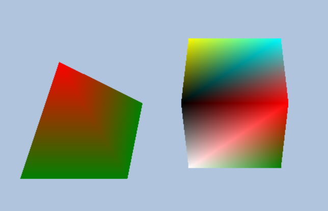
最终结果:
练习5 练习11

三角形内的像素通过 三个顶点的属性插值得到
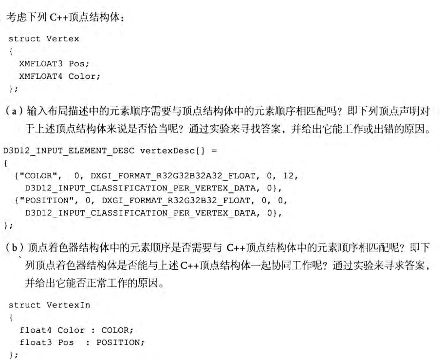
这两种都是能正常工作的
第一种虽然color 与 pos排列的顺序变了
但是它们与顶点结构体元素的偏移还是对应的
第二种 顶点着色器 与 顶点结构体的对应是通过语义来间接对应的 所以交换顺序也不会影响
练习12 调整视口 练习13 裁剪测试
视口修改:
mScreenViewport.TopLeftX = 0;
mScreenViewport.TopLeftY = 0;
mScreenViewport.Width    = static_cast<float>(mClientWidth);
mScreenViewport.Height   = static_cast<float>(mClientHeight);
mScreenViewport.MinDepth = 0.0f;
mScreenViewport.MaxDepth = 1.0f;
裁剪修改:
mScissorRect = { 0, 0, mClientWidth, mClientHeight };
练习10 14 15 16 略
- 当非遗邂逅漫展,《如鸢》带来的这场国风联动吸睛无数 2024-10-05
- Rogue牌组构建游戏《Deck of Haunts》Steam页面开放! 2024-10-05
- 炉石传说十周年解谜卡背获得攻略 2024-10-05
- 《绝地求生》工作室获授权将开发《幻兽帕鲁》手游! 2024-10-04
- 像素风冒险《乌鸦国度》主机版宣传片公开!10月发售 2024-10-04
- 世界计划缤纷舞台feat初音未来台服下载地址及游戏介绍 2024-10-03
- 动作RPG《切尔诺贝利人2:禁区》试玩预告片 首曝! 2024-10-03
- 七,MyBatis-Plus 扩展功能:乐观锁,代码生成器,执行SQL分析打印(实操详细使用) 2024-10-02


